
laPitop - Part 2
2021-12-05
If you haven't read it, I suggest you start with Part 1.
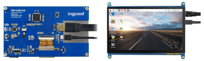
In the last part I introduced the concept of the project and talked about some of the components I picked and why. In this part I want to talk about the case design and some of the considerations with that. Before I do that, though I wanted to mention some changes I made to the parts list. The first change I made was to swap out the screen for an Ingcool 7 inch HDMI screen. The Ingcool screen had 2 benefits over the screen I was using before. The first was that the mounts were on the back, not sticking out of the sides. This allowed me to shrink the cavity the screen sat in, making the frame of the screen case much stronger and more rigid, which would make things easier on the hinges. The second, and biggest, benefit of the Ingcool screen was the fact that the HDMI and USB connections on the screen were inset into the back of the screen instead of sticking out of the side. This meant huge savings in the size of the cavity the screen sat in and no custom cabling for the video connection.
The second change I made was to swap out the Makerfocus RPI Pack V3 for the slightly newer V3P. The big change here is the addition of a 4 pin PH2.0 connector to provide an "external" power switch and power LED. That would remove the need to modify the board to add a power switch that reaches to the outside of the case, or to find a way to make the power switch on the board accesible from outside of the case. It also came with a 10000mah lipo battery, but it's physical footprint doesn't fit into the case as it is currently designed, so I'll be sticking with the 4000mah battery that came with the V3. Now, on to the case! The design goal was to be as small as possible but allow ample space to work in if necessary. It would need to be big enough to hold the Raspberry Pi itself, the RPI Pack V3(P) board, a lipo battery, and any cables and connectors required. Standoffs were created to mount the Pi and RPI Pack. The RPI Pack was mounted higher to provide clearance for the HDMI cable to plug into the Pi. With the switch from the RPI Pack V3 to V3P I also needed to add an additional space for both a power switch and room to run the cables for both the switch and a power LED.
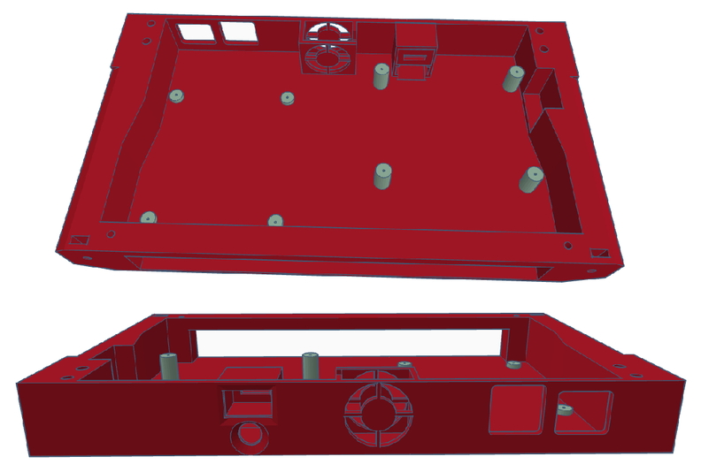
Openings were provided for the ethernet port and the USB 3.0 ports of the Raspberry Pi. The USB 2.0 ports are not exposed, since I "moved" those ports further into the case to facilitate plugging in the screen's USB cable (for both power and touch capabilities) and the receiver for the wireless mini keyboard. I also created a place for power to be provided to the system vi a USB C connector, and under that I created a space to mount a latching push button as a power switch (I went with these). And, since the Pi will be enclosed in the case, airflow was a concern as well. To address this I added a holder for a 20mmx20mmx10mm 5v fan. Air is drawn into the case through vents in the front bezel of the case, which is attached with two screws. I made the bezel removable to allow access to the microSD card in the Pi and the lipo battery attached to the RPI Pack. The keyboard sits in a tray that mounts over the top of the case, and a cover then sits over that, sandwiching the keyboard pcb and the rubber key mat together. The screen case is a simple design, a tray that the screen sits in, with a cover that screws over the front. An X shaped piece fits over the back of the case as both aesthetics and to help hide screws/bolts. The purple ring inset into the front cover was a design decision from Maker Rachel, my older niece. She suggested it would look better so we went with it!
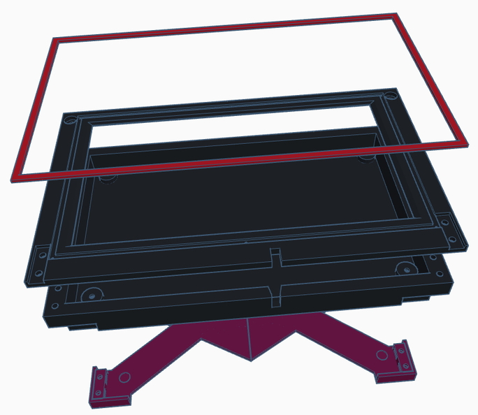
The biggest remaining part to sort out was the hinges. They would have to be friction hinges that hold their position. After testing a few different hinges, I settled on these. They were a good size and were tight without being unmovable. The hinges are inset into the body and lid so they mount flush with the faces of the case. With the case design complete, except for some tweaks as I go, it was time to start on the assembly of the prototype and that means working the wiring and any custom parts that need to be created, including a fan control circuit. I'll go into those in the next part, and hopefully after that I'll have a working mini laptop prototype!